iTaSC wiki
iTaSC (instantaneous Task Specification using Constraints) is a framework to generate robot motions by specifying constraints between (parts of) the robots and their environment. iTaSC was born as a specification formalisms to generalize and extend existing approaches, such as the Operational Space Approach, the Task Function Approach, the Task Frame Formalism, geometric Cartesian Space control, and Joint Space control.
The iTaSC concepts apply to specifications in robot, Cartesian and sensor space, to position, velocity or torque-controlled robots, to explicit and implicit specifications, and to equality and inequality constraints. The current implementation, however, is currently still limited to the velocity control and equality constraints subset. 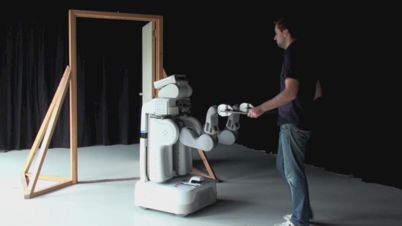
Warning
the documentation effort lags behind the conceptual and implementation effort, the best documentation can be found in our papers! (see Acknowledging iTaSC and literature)
It is currently highly recommended to use the Devel branch, a formal release is expected soon (iTaSC DSL and stacks).
Please post remarks, bug reports, suggestions, feature requests, or patches on the orocos users/dev forum/mailinglist.
What is iTaSC?
The iTaSC-Skill framework
iTaSC stands for instantaneous Task Specification using Constraints, which is developed at the K.U.Leuven during the past years [1,2,5].The framework generates motions by specifying constraints in geometric, dynamic or sensor-space between the robots and their environment. These motion specifications constrain the relationships between objects (object frames) and their features (feature frames). Established robot motion specification formalisms such as the Operational Space Approach [3], the Task Function Approach [6], the Task Frame Formalism [4], Cartesian Space control, and Joint Space control are special cases of iTaSC and can be specified using the generic iTaSC methodology.
The key advantages of iTaSC over traditional motion specification methodologies are:
- composability of partial constraints: multiple constraints can be combined, hence the constraints can be partial, they do not have to constrain the full 6D relation between two objects;
- reusability of constraint specification: the constraints specify a relation between feature frames, that have a semantic meaning in the context of a task, implying that the same task specification can be reused on different objects;
- automatic derivation of the control solution: the iTaSC methodology generates a robot motion that optimizes the constraints by automatically deriving the controllers from that constraint specification.
- weights and priorities: different constraints can be weighted or given priorities.
These advantages imply that the framework can be used for any robotic system, with a wide variety of sensors.
In order not to be limited to one single instantaneous motion specification, several iTaSC specifications can be glued together via a so-called Skill that coordinates the execution of multiple iTaSCs, and configures their parameters. Consequently, the framework separates the continuous level of motion specification from the discrete level of coordination and configuration. One skill coordinates a limited set of constraints, that together form a functional motion. Finite State Machines implement the skill functionality.
This framework is implemented in the iTaSC software.
References
- [1] J. De Schutter, T. De Laet, J. Rutgeerts, W. Decre, R. Smits,E. Aertbelien, K. Claes, and H. Bruyninckx. Constraint-based task specification and estimation for sensor-based robot systems in the presence of geometric uncertainty. The International Journal of Robotics Research, 26(5):433–455, 2007.
- [2] W. Decre, R. Smits, H. Bruyninckx, and J. De Schutter. Extending iTaSC to support inequality constraints and non-instantaneous task specification. In Proceedings of the 2009 IEEE International Conference on Robotics and Automation, pages 964–971, Kobe, Japan, 2009.
- [3] O. Khatib. The operational space formulation in robot manipulator control. In Proceedings of the 15th International Symposium on Industrial Robots, pages 165–172, Tokyo, Japan, 1985.
- [4] M. T. Mason. Compliance and force control for computer controlled manipulators. IEEE Transactions on Systems, Man, and Cybernetics, SMC-11(6):418–432, 1981.
- [5] J. Rutgeerts. Constraint-based task specification and estimation for sensor-based robot tasks in the presence of geometric uncertainty. PhD thesis, Department of Mechanical Engineering, Katholieke Universiteit Leuven, Belgium, 2007.
- [6] C. Samson, M. Le Borgne, and B. Espiau. Robot Control, the Task Function Approach. Clarendon Press, Oxford, England, 1991.
- [7] R. Smits and H. Bruyninckx. Composition of complex robot applications via data flow integration. In Proceedings of the IEEE International Conference on Robotics and Automation, pages 5576–5580, Shangai, China, 2011.
Acknowledging iTaSC and literature
Please cite following papers when using ideas or software based on/ of iTaSC:
acknowledging iTaSC paradigm/concept
Original concept
- J. De Schutter, T. De Laet, J. Rutgeerts, W. Decre, R. Smits,E. Aertbelien, K. Claes, and H. Bruyninckx. Constraint-based task specification and estimation for sensor-based robot systems in the presence of geometric uncertainty. The International Journal of Robotics Research, 26(5):433–455, 2007.
Extensions
- W. Decre, R. Smits, H. Bruyninckx, and J. De Schutter. Extending iTaSC to support inequality constraints and non-instantaneous task specification. In Proceedings of the 2009 IEEE International Conference on Robotics and Automation, pages 964–971, Kobe, Japan, 2009.
- Decré, W., De Schutter, J., Bruyninckx, H. (2013). Extending the Itasc Constraint-Based Robot Task Specification Framework to Time-Independent Trajectories and User-Configurable Task Horizons. In : Proceedings of the 2013 International Conference on Robotics and Automation (ICRA), Karlsruhe, May 2013, 1941-1948
- impedance/force/hybrid control, haptics... see below 'Papers on iTaSC applications'
Bibtex
@Article{            DeSchutter-ijrr2007,
  author          = {De~Schutter, Joris and De~Laet, Tinne and
                     Rutgeerts, Johan and Decr\'e, Wilm and Smits, Ruben and
                     Aertbeli\"en, Erwin and Claes, Kasper and
                     Bruyninckx, Herman},
  title           = {Constraint-Based Task Specification and Estimation
                            for Sensor-Based Robot Systems in the Presence of
                     Geometric Uncertainty},
  journal         =  {The International Journal of Robotics Research},
  volume          = {26},
  number          = {5},
  pages           = {433--455},
  year            = {2007},
  keywords        = {constraint-based programming, task specification,
                     iTaSC, estimation, geometric uncertainty}
}

@InProceedings{     decre09,
 author           = {Decr\'e, Wilm and Smits, Ruben and Bruyninckx, Herman
                     and De~Schutter, Joris},
 title            = {Extending {iTaSC} to support inequality constraints
                     and non-instantaneous task specification},
 title            = {Proceedings of the 2009 IEEE International Conference on
Robotics and Automation},
 booktitle        = {Proceedings of the 2009 IEEE International Conference on
Robotics and Automation},
 year             = {2009},
 address          = {Kobe, Japan}
 pages            = {964--971},
 keywords         = {constraint-based programming, task specification, iTaSC,
                     convex optimization, inequality constraints, laser tracing}
}

@InProceedings{     DecreBruyninckxDeSchutter2013,
 author           = {Decr\'e, Wilm and and Bruyninckx, Herman and De~Schutter, Joris},
 title            = {Extending the {Itasc} Constraint-Based Robot Task Specification Framework to Time-           Independent Trajectories and User-Configurable Task Horizons},
 title            = {Proceedings of the  IEEE International Conference on Robotics and Automation},
 booktitle        = {Proceedings of the  IEEE International Conference on Robotics and Automation},
 year             = {2013},
 address          = {Karlsruhe, Germany}
 pages            = {1933--1940},
 keywords         = {constraint-based programming, task specification, human-robot cooperation}
}
acknowledging iTaSC software
- D. Vanthienen, M. Klotzbuecher, T. De Laet, J. De Schutter, and H. Bruyninckx, Rapid application development of constrained-based task modelling and execution using domain specific languages, in Proc. IEEE/RSJ Int. Conf. Int. Robots and Systems, Tokyo, Japan, 2013, pp. 1860–1866.
- Vanthienen, D., De Laet, T., Decré, W., Bruyninckx, H., De Schutter, J. (2012). Force-Sensorless and Bimanual Human-Robot Comanipulation. 10th IFAC Symposium on Robot Control. international symposium on robot control. Dubrovnik, Croatia, 5-7 September 2012 (art.nr. 127)
- Smits, R., Bruyninckx, H., De Schutter, J. (2009). Software support for high-level specification, execution and estimation of event-driven, constraint-based multi-sensor robot tasks. In : Proceedings of the 14th International Conference on Advanced Robotics. International Conference on Advanced Robotics. Munich, June 22-26, 2009
Bibtex
@inproceedings{     vanthienenIROS2013,
  author          = {Vanthienen, Dominick and Klotzbuecher, Markus and De~Laet,      Tinne and De~Schutter, Joris and Bruyninckx, Herman},
  title           = {Rapid application development of constrained-based task modelling and execution using Domain Specific Languages},
  booktitle       = {Proceedings of the 2013 IEEE/RSJ International Conference on Intelligent Robots and Systems},
  title           = {Proceedings of the 2013 IEEE/RSJ International Conference on Intelligent Robots and Systems},
  organization    = {IROS2013},
  year            = {2013},
  address         = {Tokyo, Japan}
  pages           = {1860--1866}
}

@inproceedings{      vanthienen_syroco2012,
  title           = {Force-Sensorless and Bimanual Human-Robot Comanipulation},
  author          = {Vanthienen, Dominick and De~Laet, Tinne and Decr\'e, Wilm and Bruyninckx, Herman and         De~Schutter, Joris},
  booktitle       = {10th IFAC Symposium on Robot Control (SYROCO)},
  year            = {2012},
  month           = {September, 5--7},
  address         = {Dubrovnik, Croatia},
  volume          = {10}
}

@InProceedings{    SmitsBruyninckxDeSchutter2009,
  author          = {Smits, Ruben and Bruyninckx, Herman and De~Schutter, Joris},
  title           = {Software support for high-level specification, execution and estimation of event-driven, constraint-based multi-sensor robot tasks},
  booktitle       = {Proceedings of the 2009 International Conference on Advanced Robotics},
  title           = {Proceedings of the 2009 International Conference on Advanced Robotics},
  year            = {2009},
  address         = {Munich, Germany}
  pages           = {},
  keywords        = {specification, itasc, skills}
}
Literature
Papers on iTaSC applications
- Smits, R., De Laet, T., Claes, K., Bruyninckx, H., De Schutter, J. (2008). iTASC: a tool for multi-sensor integration in robot manipulation. In : Proceedings of the Multisensor fusion and integration for intelligent systems, Seoul, Korea, Aug 20-22, 2008 (pp. 445-452)
- De Laet, T., Smits, R., Bruyninckx, H., De Schutter, J. (2012). Constraint-based task specification and control for visual servoing application scenarios. Automatisierungstechnik, 60(5), 260-269
- Borghesan, G., Willaert, B., De Laet, T., De Schutter, J. (2012). Teleoperation in Presence of Uncertainties: a Constraint-Based Approach. Symposium on robot control. Dubrovnik, Croatia, 5-7 September 2012
- Vanthienen, D., De Laet, T., Decré, W., Bruyninckx, H., De Schutter, J. (2012). Force-Sensorless and Bimanual Human-Robot Comanipulation. In : 10th IFAC Symposium on Robot Control, 10. IFAC Symposium on Robot Control. Dubrovnik, Croatia, 5-7 September 2012 (pp. 1-8). IFAC
- Borghesan, G., Willaert, B., De Schutter, J. (2012). A constraint-based programming approach to physical human-robot interaction. In : IEEE International Conference on Robotics and Automation (ICRA), 2012 (pp. 3890-3896)
related papers
- Klotzbücher, M., Smits, R., Bruyninckx, H., De Schutter, J. (2011). Reusable Hybrid Force-Velocity controlled Motion Specifications with executable Domain Specific Languages. In : 2011 IEEE/RSJ INTERNATIONAL CONFERENCE ON INTELLIGENT ROBOTS AND SYSTEMS, San Francisco, USA., 25-30 September, 2011 IEEE
- Klotzbücher, M., Bruyninckx, H. (2012). Coordinating Robotic Tasks and Systems with rFSM Statecharts. JOSER: Journal of Software Engineering for Robotics, 3 (1), 28-56.
Phd's
- J. Rutgeerts. Constraint-based task specification and estimation for sensor-based robot tasks in the presence of geometric uncertainty. PhD thesis, Department of Mechanical Engineering, KU Leuven, Belgium, 2007
- R. Smits, “Robot skills: design of a constraint-based methodology and software support,” Ph.D. dissertation, Dept. Mech. Eng., KU Leuven, Belgium, May 2010
Workshops
- Vanthienen, D., De Laet, T., De Schutter, J., Bruyninckx, H. (2013). Software framework for robot application development: a constraint-based task programming approach. IEEE International Conference on Robotics and Automation SDIR workshop. Karlsruhe, 6 May 2013.
- Vanthienen, D., Robyns, S., Aertbeliën, E., De Schutter, J. (2013). Force-sensorless robot force control within the instantaneous task specification and estimation (iTaSC) framework. Benelux Meeting on Systems and Control. Houffalize, Belgium, 26-28 March 2013.
- Vanthienen, D., De Laet, T., Decré, W., De Schutter, J. (2013). Acceleration- vs. velocity-resolved constraint-based instantaneous task specification and estimation (iTaSC). Benelux Meeting on Systems and Control 2013. Houffalize, Belgium, 26-28 March 2013.
- Vanthienen, D., De Laet, T., Decré, W., Smits, R., Klotzbücher, M., Buys, K., Bellens, S., Gherardi, L., Bruyninckx, H., De Schutter, J. (2011). iTaSC as a unified framework for task specification, control, and coordination, demonstrated on the PR2. IEEE/RSJ International Conference on Intelligent Robots and Systems. San Francisco, 25-30 September 2011.
- Vanthienen, D., De Laet, T., Smits, R., Buys, K., Bellens, S., Klotzbücher, M., Bruyninckx, H., De Schutter, J. (2011). Demonstration of iTaSC as a unified framework for task specification, control, and coordination for mobile manipulation. IEEE/RSJ International Conference on Intelligent Robots and Systems. San Francisco, 25-30 September 2011.
More detailed list of literature
iTaSC is not iTaSK
Remark the common mistake in the naming, it is iTaSC (instantaneous Task Specification using Constraints), not iTASK.The iTaSC Software
The software implements the iTaSC-Skill framework in Orocos, which is integrated in ROS by the Orocos-ROS-integration [1]. The Real-Time Toolkit (RTT) of the Orocos project enables the control of robots on a hard-realtime capable operating system, e.g. Xenomai-Linux or RTAI-Linux. The rFSM subproject of Orocos allows scripted Finite State Machines, hence Skills, to be executed in hard realtime. The figure below shows the software architecture, mentioning the formulas for the resolved velocity case without prioritization for clarification. The key advantages of the software design include:
- the modular design, allowing users to implement their own solver, scene graph, motion generators ...,
- the modular task specification that allows users to reuse tasks, and enables a future task-web application to down- or upload tasks,
- the flexible user interface, allowing users to change the weights and priorities of different constraints, and to add or remove constraints.
Furthermore, the Bayesian Filtering Library (BFL) and Kinematics and Dynamics Library (KDL) of the Orocos project are used to retrieve stable estimates out of sensor data, and to specify robot and virtual kinematic chains respectively.
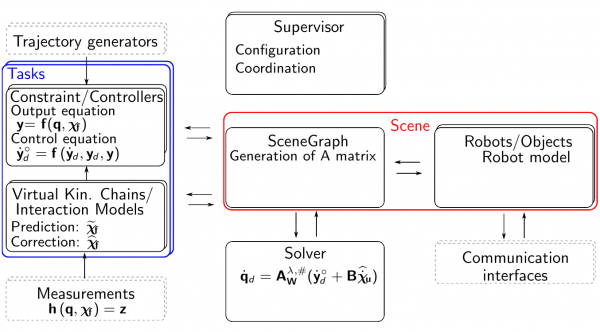 iTaSC framework scheme
License
The iTaSC software is licensed under a dual LGPLv2.1/BSD license. You may redistribute this software and/or modify it under either the terms of the GNU Lesser General Public License version 2.1 (LGPLv2.1) or (at your discretion) of the Modified BSD License.Acknowledgements
The developers gratefully acknowledge the financial support by:- European FP7 project Rosetta (FP7-230902, Robot control for skilled execution of tasks in natural interaction with humans; based on autonomy, cumulative knowledge and learning)
- European FP7 project BRICS (FP7-231940, Best practices in robotics)
- KU Leuven's Concerted Research Action GOA/2010/011 Global real-time optimal control of autonomous robots and mechatronic systems
- Flemish FWO project G040410N Autonome manipulatietaken met een vliegende robot. (Autonomous manipulation with a flying robot.)
Roadmap
We are interested in (contributions to):- Include other types of constraints, eg. inequality constraints
- Expand the capabilities to include uncertainty constraints (and make a nice example/tutorial)
- Include resolved acceleration control
- Make more tutorials and examples (eg. including MTTD)
- ...
(to be expanded)
References
- [1] R. Smits and H. Bruyninckx. Composition of complex robot applications via data flow integration. In Proceedings of the IEEE International Conference on Robotics and Automation, pages 5576–5580, Shangai, China, 2011.
iTaSC DSL: rapid iTaSC application development
iTaSC DSL is a Domain Specific Language for constraint-based programming, more specifically iTaSC.
- The DSL provides a formal model for iTaSC applications, that also serves as a design template and guideline.
- It provides a 'scripting language' to model an iTaSC application. This reduces the effort of creating an iTaSC application wrt. the previous labour intensive process of editing multiple files.
- The DSL is not just a scripting language, but a formal model. A model of an iTaSC application (M1 level model) can be checked for conformity to the iTaSC model (M2 level model). These checks occur before running the application, and return meaningful errors instead of (obscure) run-time errors, hence reducing debugging efforts.
- An iTaSC application model can be 'executed/parsed' to running code.
For more explanation and examples, please read D. Vanthienen, M. Klotzbuecher, T. De Laet, J. De Schutter, and H. Bruyninckx, Rapid application development of constrained-based task modelling and execution using domain specific languages, in Proc. IEEE/RSJ International Conference on Intelligent Robots and Systems (IROS), Tokyo, Japan, 2013, pp. 1860–1866.
Videos and links
http://people.mech.kuleuven.be/~dvanthienen/IROS2013/Code
The code, including examples can be found on: http://bitbucket.org/dvanthienen/itasc_dslIt is recommended to use the devel branch for the DSL as well as the iTaSC stacks.
Running examples
In a typical use case, you'll interact with the running application through events.For the Orocos reference implementation (in a ROS environment): One way is to send events in the Orocos task browser through the event_firer component that is automatically started when parsing and deploying an application.
Another, more user-friendly way, is to send events on the /itasc/ ros_common_events_in ROS topic (see README of the itasc_dsl repository).
A GUI to send events can be found on: https://bitbucket.org/apertuscus/python_gui
Look for an example at the itasc_erf2012_demo, that contains a run_eventgui.sh, launching this GUI with events for the iTaSC ERF2012 tutorial.
iTaSC quick start
Overview
The framework is ordered following a OROCOS-ROS approach and consists of 1 meta-stack:- itasc: This ROS unary stack serving as a meta-stack, it's purpose is to keep the framework stacks together
This meta-stack consists of following stacks:
- itasc_core: This ROS unary stack contains the core functionality of iTaSC: the scene and template (headers) for all itasc component types (solvers, virtual kinematic chains, controller/constraints, robots, objects)
- itasc_solvers: Contains a number of solver packages for iTaSC
- itasc_robots_objects: Contains a number of robot and object packages for iTaSC
- itasc_tasks: Contains a number of task packages for iTaSC (combination of virtual kinematic chains and constraint/controllers)
Each package contains the following subdirectories:
- src/ containing the source code of the components (C++)
- cpf/ containing the property files for the components and FSM's
- scripts/ containing the FSM's and components in a LUA implementation (eg. Supervisors)
- launch/ containing eventual ROS launch files
Code
The installation instructions further on will cover the installation of the source code and dependencies.Dependencies
- Orocos toolchain 2.5.0 and up
- kdl_lua of the rtt_geometry stack
- Orocos Kinematics and Dynamics Library 0.2.3 and up
- Eigen 2 or higher
- rFSM
- ROS: optional for the core infrastructure of iTaSC, however used in all examples and tutorials, as well as the easy setup scripts.
Source code
Source code of iTaSC can be found on following git repositories:https://gitlab.mech.kuleuven.be/groups/rob-itasc
and for the iTaSC DSL
https://bitbucket.org/dvanthienen/itasc_dsl.git
Installation instructions for ROS Indigo
''The following explanation uses the ROS workspace and rosinstall tools, it is however easy to follow the same instructions without these tools, as will be hinted further on. IMPORTANT: All packages are catkin-based.
Pre-requisites
- ROS Indigo
- Orocos (installation instructions on https://github.com/orocos/rtt_ros_integration)
- rtt_ros_integration (https://github.com/orocos/rtt_ros_integration)
- geometry (https://github.com/ros/geometry)
- robot-model (https://github.com/ros/robot_model)
- rtt_geometry (https://github.com/orocos/rtt_geometry)
- orocos_kinematics_dynamics (https://github.com/orocos/orocos_kinematics_dynamics)
- IMPORTANT: You need first to install the following debian packages upon which they rely to have successful compilation:
sudo apt-get install libeigen3-dev sip-dev liburdfdom-dev ros-indigo-angles ros-indigo-tf2-ros ros-indigo-geometric-shapes liblua5.1-0 liblua5.1-0-dev collada-dom-dev libbullet-dev ros-indigo-orocos-kdl ros-indigo-orocos-kinematics-dynamics ros-indigo-orocos-toolchain ros-indigo-geometry ros-indigo-robot-model ros-indigo-rtt-geometry ros-indigo-rtt-ros-integration ros-indigo-rtt-sensor-msgs ros-indigo-rtt-visualization-msgs
- Afterwards add the following to your .bashrc file:
source /opt/ros/indigo/setup.bash
- Make a catkin workspace (for instance ~/ws):
mkdir -p ~/ws/src
cd ~/ws/src
catkin_init_workspace
cd ~/ws/
catkin_make
- Afterwards add the following to your .bashrc file underneath /opt/ros/indigo source command:
source ~/ws/devel/setup.sh
Installation file
- Download the ROS installation file here
- First copy this file into your workspace ws and then merge:
cd  ~/ws
wstool init src
wstool merge -t src itasc_dsl.rosinstall
wstool update -t src
- OR manually clone each repository mentioned in the file, switch to the correct branch/tag, and add to your ROS_PACKAGE_PATH (NOT RECOMMENDED)
Application dependent install files
The KUKA youBot and PR2 have not yet been tested in Indigo.
Setup
- Download this file, move and rename it to ~/.bash_itasc_dsl
- Add the following at the end of your ~/.bashrc file, in the here presented order
source ~/.bash_itasc_dsl
useITaSC_deb
- re-source your .bashrc
source ~/.bashrc
Build the packages
cd ~/ws/
catkin_make
Installation instructions for ROS Fuerte or Groovy
The following explanation uses the ROS workspace and rosinstall tools, it is however easy to follow the same instructions without these tools, as will be hinted further on.Pre-requisites
- ROS Fuerte or Groovy
- Orocos (installation instructions on http://wiki.ros.org/orocos_toolchain_ros)
- OR
sudo apt-get install ros-groovy-orocos-toolchain
- Install following stacks:
sudo apt-get install libeigen3-dev ros-groovy-rtt-ros-integration ros-groovy-rtt-geometry ros-groovy-rtt-common-msgs ros-groovy-rtt-ros-comm
- rosws (ROS workspace, optional but highly recommended):
- Create a new ros workspace or use an existing one
- Add the following to your .bashrc file:
source /opt/ros/groovy/setup.bash
source ~/path_to_workspace/setup.bash
Installation file
- Download the ROS installation file here
- Merge this file into your workspace:
rosws merge itasc_dsl.rosinstallrosws update
- OR manually clone each repository mentioned in the file, switch to the correct branch/tag, and add to your ROS_PACKAGE_PATH
Application dependent install files
- When using the KUKA youBot:
- Download the ROS installation file here
rosws merge itasc_youbot_fuerte.rosinstallrosws update
Setup
- Download this file, move and rename it to ~/.bash_itasc_dsl
- Add at the following at the end of your ~/.bashrc file, in following order:
source /path/to/your/rosworkspace/setup.bashsource .bash_itasc_dsluseITaSC_deb
- re-source your .bashrc
source ~/.bashrc
For your convenience we put here some extra instructions for commonly used platforms:
When using a PR2 robot
This assumes you have PR2 related packages installed, see PR2 installation.- Go to your ros workspace
- Create the rtt pr2 controller messages and add it to your ros workspace
rosrun rtt_rosnode create_rtt_msgs pr2_controllers_msgsrosws set rtt_pr2_controllers_msgs
- Convert the following XACRO scripts:
roscd itasc_pr2./convert_xacro.sh
When using a KUKA YouBot robot
This assumes you have KUKA YouBot related packages installed, see for example ERF 2012 laser tracing tutorial.- add the location of YouBot related lua files to your LUA_PATH:
- uncomment the line mentioning 'youbot_driver_rtt' in ~/.bash_itasc_dsl
Build the packages
Build the core packages
rosmake itasc_core trajectory_generators itasc_tasks rFSM rttlua_completion itasc_solvers fixed_object itasc_robot_object moving_object moving_object_tf
Build application dependent packages
- Compile the dedicated itasc components for the PR2 or Youbot, located in the itasc_robots_objects stack
- To compile for all supported platforms:
rosmake itasc
Test the installation
- Easy application on a PR2: (TODO move to tutorials/dsl readme)
- start a real or simulated PR2. For the simulated environment:
roslaunch pr2_gazebo pr2_empty_world.launch
- Go to the itasc_dsl package and run the bunny pose example
roscd itasc_dsl./run_bunny.sh- This should move the arms in a grippers down 'bunny' pose
- Play around the task browser or manually quit the application using CTRL+d
- start a real or simulated PR2. For the simulated environment:
- The itasc_dsl package contains more example models to try out
- Interaction with a running iTaSC application happens through events, multiple options exist (see ERF 2012 laser tracing tutorial for an example):
- sending events using a python Qt GUI: see python_gui
- sending events on a ROS topic
- sending events using the Orocos event_firer (automatically loaded when using the DSL parser)
- Follow one of the tutorials (deprecated, needs update)
- For known compatibility issues: see below
Design Workflow
Multiple files should be created or adapted to create a new application, a good workflow could be:- Make a list of all tasks that have to be executed
- Draw the kinematic loops for each task (see also Comanipulation Demo)
- Draw the component layout of your application
- Draw the behavior of your application (coordination of the behavior at runtime), this will afterwards be implemented in the composite_task_fsm.lua and the running_task_fsm.lua files. Consult 'subFSM's of the running state' of the iTaSC user guide for more information.
- Create or download all necessary packages (tasks, robots, objects, solvers...)
- Create the components (computational part)
- Create the skills (FSM: coordination and configurational part), but leave the sub state machines dictating behavior at runtime for now (eg. running_taskname_fsm.lua).
- Create the FSM on the iTaSC level: itasc_configuration.lua
- Create the FSM on the application level
- Check, create or adapt the configuration files (.cpf) of your components.
- Create a deploy script: run.ops and run.sh (after this step, you can test that your application gets to the running state, without errors)
- Create the FSMs that coordinate the behavior at runtime
- on itasc level: composite_task_fsm.lua
- on task level (for each task): running_taskname_fsm.lua
Known compatibility issues
- robot_model/kdl_parser from the ROS Groovy debian packages: downgrade to robot_model-1.8
- used in itasc_pr2 and itasc_robot_object to convert urdf model to kdl tree
- this version returns foo-bar tree
- prevents itasc_pr2 and itasc_robot_object components to configure
- In case your computer has limited RAM (2GB):
- In .bashr file: add
export ROS_PARALLEL_JOBS=' -j1 -l1' - When performing rosmake:
rosmake --threads 1
- In .bashr file: add
iTaSC user guide
Creating an iTaSC application
The iTaSC main manual is currently in pdf version, until the wiki version is finished.Computation
See pdf manualConfiguration and coordination: Skills
What is a skill?
A Skill is a specific combination of the configuration and coordination of Tasks. An iTaSC skill is implemented in the framework using the Lua based rFSM Finite State Machine (FSM) engine. The following design rules should be/are applied:- Event driven: Events trigger the FSMs to transition from one state to another.
- Each FSM should be designed such that it is framework independent (e.g. from OROCOS RTT).
- Each FSM is loaded in a Supervisor component, that contains the OROCOS (RTT) specific parts of the FSM.
The 3 FSM levels
There are 3 levels of FSM for an iTaSC application (hierarchical state machine):- Application: The state machine of this level takes care of the behavior of the whole system: it configures and coordinates components not part of iTaSC (e.g. hardware interfaces and trajectory generators) and iTaSC as one composite component. The application developer takes care of the first part and sends (the fixed set of) events to configure and coordinate the iTaSC composite component. The transitions of the application state machine are always triggered by the a “done” signal raised by the iTaSC FSM (i.e. “e_ITASCConfigured” event, see 1.4) and additionally by user defined events that are raised by non-iTaSC components (i.e. hardware ready).
- iTaSC: The state machine of this level configures and coordinates the behavior of iTaSC components. It has a fixed structure, leaving two parts to be specified by the application developer ("user"). Firstly, the user must specify the description of the scene and the composition of the kinematic loops in the configuration file (“itasc_configuration.lua”). This file DOES NOT describe the actual behavior of the task but the components which are involved (Composition). Secondly, the subFSM part of the running state must be defined. The running state of the state machine is composed by two parts: the first coordination part is fixed and takes care of running all iTaSC components in the right order (actually making iTaSC components running as a composite component, from the user perspective), the second, the subFSM part (highlighted in green in fig The 3 FSM levels), specifies the high level workflow of the task. This second sub-state machine defines the transitions between the tasks.
- Task: The state machine of this level contains a more concrete coordination of the task: while the previous level abstracts from task specifics, here, the actual triggers to change the characteristics of the iTaSC components must be implemented (i.e. assignment of property values, etc.) see 1.5 for an example.
These levels are not only present on the configuration/coordination but also on the computational level (see slides). As hinted before your application FSM will only 'see' the components 'outside' iTaSC (robot drivers, sensor components...) and iTaSC as one composite component. Similarly, the iTaSC FSM 'sees' a task as one entity. Section 'The sub-FSMs of the running state', gives a good example/effect of this distinction.
As a result of the 3 levels, your application is always in 3 states: one for each level.
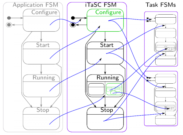 The 3 FSM levels
The structure of a FSM
In the standard implementation, a FSM of a certain level consist of 3 files, e.g. for a task:- taskname_fsm.lua: This is the actual state machine
- running_taskname_coordination.lua: This is the coordination part of the running state ensuring that the iTaSC algorithm is executed in the right order.
- running_taskname_fsm.lua: This is the sub-FSM part of the running state. This part should be edited to implement the behavior of the running application.
The coordination and FSM part of the running state are executed sequentially. The full FSM is loaded in a supervisor component: taskname_supervisor.lua
On the iTaSC level, composite_task_fsm.lua is used instead of running_itasc_fsm.lua, to highlight its meaning. There is also an additional file: itasc_configuration.lua, which is part of the configuration state of the itasc_fsm.lua.
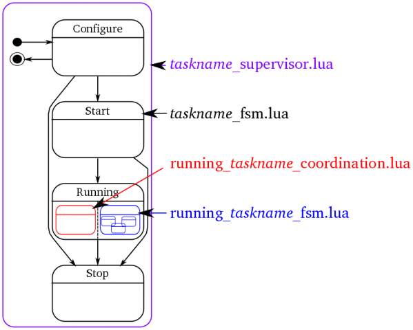 FSM structure
The state machine implemented in name_fsm.lua is a composite state machine, consisting of two states:
- NONemergency state: is a subFSM, containing the actual state machine, as shown in the figure above,
- emergency state: an 'e_emergency' event is fired by one of the FSMs or components, in case of a failure. This event is caught by all state machines, causing them to transition to the emergency state, leaving whatever state the NONemergency sub state machine is in.
This structure can be found in all statemachines of all levels (except for the application FSM, where the division of the running state is not (always) necessary).
The event-transition flow
In order to get your application running, the application has to be configured and started. After running, you also want it to stop (. Moreover, these actions should happen in a coordinated way.As explained above, there are three levels: application, iTaSC and task: each of which makes abstraction of the level below it. As a result, events are propagated down the hierarchy to take effect and responses are sent back up, to acknowledge execution. The design of the Application and Task FSM should comply with the same rationale (i.e. each transition is triggered by the lower level FSM). The standard event-transition flow consists of:
- (every component initializes at start-up, without the need for an event)
- the application level FSM transitions to the configuring state, after initialization. In this state, all application level components are configured and an event is sent ("e_configITASC"), to which the iTaSC level FSM will react by transitioning to the configuring state.
- The iTaSC level FSM, now in its configuring state, will on his turn configure the iTaSC level components and send an event ("e_configTasks") that triggers the tasks to get to the configuring state.
- the task level FSMs (also in the configuring state now) on their turn will configure the task level components. After successful completion, the task level FSMs will transition to the configured state and send out an event to acknowledge this completion of the configuration.
- When all tasks and iTaSC level components indicated a successful configuration, the iTaSC level FSM will transition to the configured state and send out an "e_ITASCConfigured" event.
- When all application level components indicate a successful configuration and this "e_ITASCConfigured" event is received, the application level FSM will transition to the application configured state.
- After an event triggering the transition of the application level FSM from the configured state to the starting state (in the most examples, just an e_done = completion of the configured state actions), a similar event-transition flow follows for the starting-started states.
The flow for the stopping-stopped states is also similar. The running states are different in the sense that there is no 'ran state': the state machines will stay in the running state until they are stopped.
The sub-FSMs of the running state
The actual behavior of the application at runtime, is governed by the sub state machines of the running states of each level, which form a hierarchical state machine. The idea is that a high(er) level description is implemented in the composite_task_fsm.lua. The actual behavior of the individual tasks is governed by a separate sub-state machine for each task, running_taskname_fsm.lua. In other words: the composite_task_fsm coordinates the behavior between the different tasks. The running_taskname_fsm coordinates the behavior of the task.The following figure gives an example of the composite task and tasks in case of the simultaneous laser tracing on a table and a barrel example, used in previous paragraphs. The goal is to (in this order):
- Move to a certain starting pose (position and orientation)
- Trace a sine on a table and a circle on a barrel, if a barrel is detected
- Trace a sine on a table, if no barrel is detected.
In the figure, a (sub-)FSM is represented by a purple rounded box, a state by a rounded black box and a possible state transition by an arrow. State transitions are triggered by an event or combination of events. The state transitions of the task subFSMs, indicated by a colored arrow and circle, are caused by the event with the corresponding color, fired in the composite_task_fsm.lua.
To prevent overloading the figure, only a limited number of actions is shown, e.g. only the entry part of the state and not the exit part (which will, e.g. deactivate the trajectory generator and tasks which were activated). 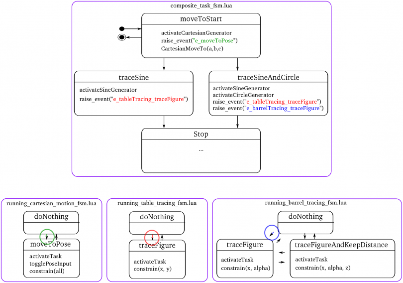 SubFSMs of the running state
The composite state of the example in the figure consists of 4 states.
- The initial state is the "moveToStart" state,
- which activates the needed trajectory (actually a set point generator),
- raises an event to cause the needed cartesian_motion task to reach a "moveToPose" state
- and then calls the Lua function "CartesianMoveTo()", which is implemented in the itasc_supervisor.lua (no RTT specifics in the statemachine, remember!).
- Depending on the presence of a barrel (somehow detected, and notified to the FSMs by an event), there is a state transition to the "traceSine" or "traceSineAndCircle" state, after completing the "moveToStart" movement (notified by another event). Either of this states will
- activate the right trajectory/set point generator,
- send an event that causes the running_table_tracing_fsm.lua subFSM of the table_tracing task (and running_barrel_tracing_fsm.lua subFSM of the barrel_tracing task) to transition to a traceFigure state.
- After completion of the tracing task (or another stop-transition causing event), the composite state machine will reach a stop(ped) state.
As can be seen, the composite task FSM just sends an event to trigger the task subFSMs to reach the appropriate state. The task subFSM will take care of task specific behavior, e.g.
- selecting the feature coordinates to constrain
- activate these constraints
- change the weight of a specific constraint
- alter control parameters (gains...)
- ...
Doing so, the tasks can be easily adapted/ swapped/ changed/ downloaded.
Note: The names of the tasks are specific; i.e. they are the names of the components that are used for the tasks. The name of the task package will be more general, e.g. xyPhiThetaPsiZ_PID task (named after the structure of it's VKC and controller type). Cfr. class - object of object oriented programming.
Event types
There are currently three types of events, that differ in how they are communicated (see also 'Communication') and treated:- Common events: events that 'can wait' to be handled, together with other events, in the next update/iteration, e.g. "e_startItasc" event,
- Priority events: events that can't wait to be handled in the next update, e.g. "e_emergency" (fired in case of a failure),
- Trigger events: events that trigger other state machines or components, typically used to ensure an algorithm distributed over multiple FSM is executed during the correct time step and in the right order, e.g. "e_triggerTasks", fired by running_itasc_coordination.lua.
Composition
Communication
All communication of data, including events, is done over Orocos ports. The FSMs communicate their events by the event ports of the components they are loaded in (supervisors). There are separate ports for each type of event (in and output event-port for each type):- Common events: Communicated over a buffered connection
- Priority events: Communicated over a buffered connection on event-triggered ports
- Trigger events: Communicated over a non-buffered connection on event-triggered ports
Conventions
To automate the majority of the scripting, the following conventions are taken into account in the examples:- the components and scripts have the task name in their names, e.g. for cartesian_motion
- package name: cartesian_motion
- component names: VKC_cartesian_motion.hpp
- script names: cartesian_motion_supervisor.lua
- For conformity it is advised to use lower case names with underscores to separate words.
| Attachment | Size |
|---|---|
| iTaSC_Manual.pdf | 396.63 KB |
How to create a new task?
Please read the iTaSC_Manual first, to get acquainted with the iTaSC terminology and structure. A task is the combination of a virtual_kinematic_chain and a constraint/controller. In the iTaSC software, it is a (ROS-)package that contains:
- src/ containing the source code of the components (C++)
- VKC_taskname.hpp/cpp
- CC_taskname.hpp/cpp
- cpf/ containing the property files for the components and FSM's
- scripts/ containing the FSM's and components in a LUA implementation
- taskname_supervisor.lua: the supervisor orocos-component, containing the Orocos specific code, eg. ports to recieve/send events on...
- taskname_fsm.lua: the finite-state machine containing the actual Skill
- running_taskname_coordination.lua: the sub-finite-state machine of the running state of the task, containing the coordination part of the task, it determines what the task part of the iTaSC algorithm should do and in which order
- running_taskname_fsm.lua: the sub-finite-state machine machine of the running state of the task, determining the actual actions of the task (when to enable the task, when to change weights...)
- launch/ containing eventual ROS launch files
The running_taskname_coordination.lua and running_taskname_fsm.lua, are sub-FSM's of the running state of the task (defined in taskname_fsm.lua). They are executed sequentially, first the coordination part, then the FSM part.
Getting started
A tasks consists of a Virtual Kinematic Chain (VKC) (except for constraints on joints only) and a Constraint Controller (CC).Virtual Kinematic Chain (VKC)
A VKC inherits from VirtualKinematicChain.hpp in the itasc_core unary stack, which serves as a basic template.Important are the expected reference frames and points for the data on following ports. (o1=object 1, o2= object 2)
- Inputs
- $T_{o1}^{o2}$ = RelPose(o2|o2,o1|o1,o1) = pose of o2 on body o2 wrt. o1 on body o1 expressed in o1
- $_{o1}^{o1}t_{o2}^{o1}$ = RelTwist(o1|o1,o1,o2) = twist with ref.point o1 on object o1 expressed in o1
- Outputs
- $T_{o1}^{o2}$ = RelPose(o2|o2,o1|o1,o1) = pose of o2 on body o2 wrt. o1 on body o1 expressed in o1
- $J_{u}\chi_{u}$ =
- $_{o1}^{o2}J_{f o1}^{o1}$ = Jacobian(o1|o2,o1,o1) = ref.point o1 on object o2 expressed in o1
The expected references are also mentioned as comments in the files
Constraint/Controller (CC)
A Constraint/Controller inherits from ConstraintController.hpp in the itasc_core unary stack, which serves as a basic template.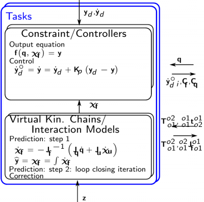 task_layout
A full template will be made available soon... At the moment, start from an example... Have a look at the keep_distance task-package (in the itasc_comanipulation_demo stack) as a good example of a task. Special cases are:
- cartesian_motion: This task, defines a virtual kinematic chain with in stead of feature coordinates x,y,z,roll, pitch, yaw, the full pose (KDL::Frame), to enhance efficiency of the code (and prevent singularity problems).A separate port, the ChifT port transfers this data from the VKC to the CC, which should be connected manually at the moment!. ChifT = RelPose(o2|o2,o1|o1,o1) = pose of o2 on body o2 wrt. o1 on body o1 expressed in w
- joint_motion: This task has no virtual kinematic chain, because its output equation is y=q. It constrains only the joint coordinates.
Conventions
To automate the majority of the scripting, the following conventions are taken into account in the examples, which is recommended to do for new tasks too:- the components and scripts have the task name in their names, eg. for cartesian_motion
- package name: cartesian_motion
- component names: VKC_cartesian_motion.hpp
- script names: cartesian_motion_supervisor.lua
- For conformity it is advised to use lower case names with underscores to separate words
How to create a new robot or object?
Should inherit from SubRobot.hpp, which can be found in the itasc_core. This file is a template for a robot or object component. See itasc_robots_objects stack for examples.
As can be seen in the examples, a robot component contains always a KDL::Tree, even if the robot is just a chain. This is to be able to use the KDL::Tree functionality, which is regrettable, not perfectly similar as the KDL::Chain functionality. E.g. tree.getSegment(string name) has a string as input, chain.getSegment(number) has a number as input, but not a string...
How to create a new solver?
Coming soon, have a look at itasc_solvers for examples.
iTaSC API
a
iTaSC tutorials
List of iTaSC tutorials Please report any issues on the orocos users or dev mailinglist
Youbot lissajous tracing tutorial (Cartesian VKC)
- Summary
- Installation
- The tutorial
- List of all tasks/motions to be executed
- Draw the kinematic loops for each task
- Draw the behavior of the application at runtime
- Create or download all necessary packages
- Create the FSM on the iTaSC level
- Create the FSM on the application level
- Check, create or adapt the configuration files of your components
- Create a deploy script
- Create the FSMs that coordinate the behavior at runtime
- Configuration of the solution of the tutorial
- Execution of the solution of the tutorial
- FAQ
Summary
This tutorial explains how to create an application to trace a Lissajous figure with a Kuka Youbot, starting from existing packages (itasc_core, robots, tasks, solvers, trajectory generators...). The code was developed by the Leuven team during the BRICS research camp 2011.Installation
Dependencies
- itasc and it's dependencies
- trajectory_generators
- youbot drivers
- ROS Electric
The easiest way to install all needed dependencies: (How to find the debian packages on ros.org)
- ROS Electric
- Orocos toolchain
sudo apt-get install ros-electric-rtt-common-msgssudo apt-get install ros-electric-rtt-ros-commsudo apt-get install ros-electric-rtt-ros-integrationgit clone http://git.mech.kuleuven.be/robotics/rtt_geometry.git
- Orocos kinematics and dynamics
sudo apt-get install ros-electric-orocos-kinematics-dynamics
- rFSM
- needs lua:
sudo aptitude install liblua5.1-0-devsudo aptitude install liblua5.1-0sudo aptitude install lua5.1git clone git://gitorious.org/orocos-toolchain/rttlua_completion.git
git clone https://github.com/kmarkus/rFSM.git
- needs lua:
- Trajectory Generators
git clone http://git.mech.kuleuven.be/robotics/trajectory_generators.git
- youbot hardware stack
git clone http://git.mech.kuleuven.be/robotics/youbot_hardware.git -b devel- this depends on:
git clone http://git.mech.kuleuven.be/robotics/soem.git
- this depends on:
git clone git://git.mech.kuleuven.be/robotics/motion_control.git -b devel
- youbot_description package of the youbot-ros-pkg (=a stack), no need to compile it! WARNING: there are two repos around, make sure you have this one!
git clone https://github.com/smits/youbot-ros-pkg.git
- iTaSC
git clone http://git.mech.kuleuven.be/robotics/itasc.gitgit clone http://git.mech.kuleuven.be/robotics/itasc_core.gitgit clone http://git.mech.kuleuven.be/robotics/itasc_solvers.gitgit clone http://git.mech.kuleuven.be/robotics/itasc_tasks.gitgit clone http://git.mech.kuleuven.be/robotics/itasc_robots_objects.git(+switch to devel branch)
Download the solution of the tutorial
git clone http://git.mech.kuleuven.be/robotics/itasc_examples.git
Setup
- It is strongly recommended that you add the following to a setup script or your .bashrc
- Make sure that all packages are added to you ROS_PACKAGE_PATH variable
- Source env.sh in the orocos_toolchain stack
- Set the LUA_PATH variable:
if [ "x$LUA_PATH" == "x" ]; then LUA_PATH=";;"; fi
if [ "x$LUA_CPATH" == "x" ]; then LUA_CPATH=";;"; fi

export LUA_PATH="$LUA_PATH;`rospack find ocl`/lua/modules/?.lua"
export LUA_PATH="$LUA_PATH;`rospack find kdl`/?.lua"
export LUA_PATH="$LUA_PATH;`rospack find rFSM`/?.lua"
export LUA_PATH="$LUA_PATH;`rospack find rttlua_completion`/?.lua"
export LUA_PATH="$LUA_PATH;`rospack find youbot_master_rtt`/lua/?.lua"
export LUA_PATH="$LUA_PATH;`rospack find kdl_lua`/lua/?.lua"

export LUA_CPATH="$LUA_CPATH;`rospack find rttlua_completion`/?.so"

export PATH="$PATH:`rosstack find orocos_toolchain`/install/bin"
- Create the youbot.urdf file out of the youbot.urdf.xacro file
cd `rospack find youbot_description`/robots/(part of the youbot-ros-pkg)rosrun xacro xacro.py youbot.urdf.xacro -o youbot.urdf
Make
rosmake itasc_youbot_lissajous_app
The tutorial
Note: The solution doesn't make use of the templates of the application and itasc level FSMs yet. The behavior should be the same, but you'll find more (copied) files in the scripts folder, than you will have created in your folder, when following this tutorial. (Don't worry, you'll notice what is copied and what not).'This tutorial explains how to create an iTaSC application, starting from existing packages. The scheme we want to create is depicted in following figure:
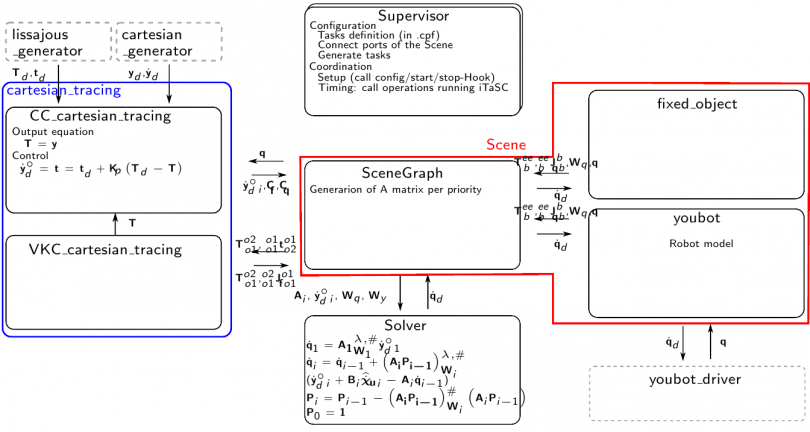 itasc_youbot_app scheme
The tutorial will follow the design workflow as explained here.
List of all tasks/motions to be executed
- Let the end effector go to a start position, with respect to a certain point in space
- Let the end effector trace a lissajous figure in the air, with respect to a certain point in space
Draw the kinematic loops for each task
The two motions are constraining the same relationship between the end effector of the robot and a fixed frame in space. Therefore, the same task can be used for both motions. The only difference is a different input from the trajectory generators. The following figures show the kinematic loop describing the task: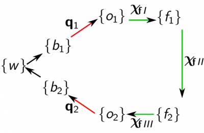 kinematic loop
 - frames
- o_1=f_1=end effector
- o_2=f_2=fixed object
- feature coordinates
- X_fI=(-)
- X_fII=in this case actually the full pose!
- X_fIII=(-)
- outputs
- y= X_f = T
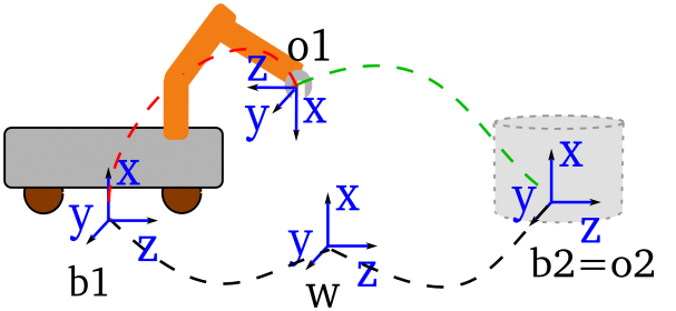 itasc_youbot_app kinematic loop
Draw the behavior of the application at runtime
This will afterwards be implemented in the composite_task_fsm.lua and the running_cartesian_tracing_fsm.lua files. Consult 'subFSM's of the running state' of the iTaSC user guide for more information. The following figure depicts the behavior of this application.In the figures, a (sub-)FSM is represented by a purple rounded box, a state by a rounded black box and a possible state transition by an arrow. State transitions are triggered by an event or combination of events. The state transitions of the task subFSM that are indicated by a colored arrow and circle, are caused by the event with the corresponding color, fired in the composite_task_fsm.lua. 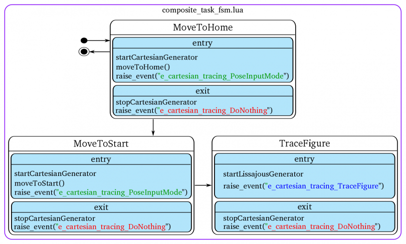 composite task FSM of the youbot_lissajous_app To automatically transition from the MoveToStart to the TraceFigure state, an event indicating that the start position is reached must be fired. This event will be generated by the 'cartesian_generator'.
 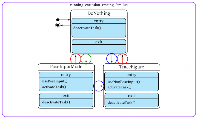 running_cartesian_tracing_fsm of the youbot_lissajous_app
Create or download all necessary packages
- general components and scripts (from the itasc_core stack)
- scene
- start from the itasc and application level script templates in the script subdir
- robots and objects (from the itasc_robots_objects stack)
- youbot: itasc_youbot package
- fixed_object: fixed_object package
- task (from the itasc_tasks stack)
- cartesian_tracing: cartesian_motion package
- solver (from the itasc_solvers stack)
- solver: wdls_prior_vel_solver package
- trajectory generators (from the trajectory_generators stack)
- cartesian_generator: cartesian_trajectory_generator package
- lissajous_generator: lissajous_generator package
Overview of the modifications needed:
- Computation: No modifications needed
- Coordination:Modifications needed
- for the specific behavior at runtime, see 'behavior at runtime'
- for the other behavior, see following sections
- Configuration: Modifications needed
- see 'Check, create or adapt the configuration files of your components'
- Communication and Composition:
- see 'Create a deploy script'
Create an empty ROS-package for your application and create 2 subdirectories:
- scripts: this subdirectory will contain the for your application adapted scripts
- cpf: this subdirectory will contain all (non-standard) property files for your application
Create the FSM of the cartesian_tracing task
A FSM on the task level consists of 3 parts (see also 'the 3 FSM levels' of the iTaSC manual), for this task:- cartesian_tracing_fsm.lua: this is the actual FSM, other files are loaded in certain states of this FSM,
- running_cartesian_tracing_coordination.lua: this part takes care of the coordination of the algorithm at runtime, it is part of the running state of the actual FSM,
- running_cartesian_tracing_fsm.lua: this part takes care of the coordination of the behavior at runtime, it is also part of the running state of the actual FSM and is executed after the coordination of the algorithm,
Templates of these files can be found in the cartesian_motion package, scripts subdirectory (cartesian_tracing is an instance of cartesian_motion).
- cartesian_tracing_fsm.lua: you can use the template without modifications: no need to change the name, just use cartesian_motion_fsm.lua,
- running_cartesian_tracing_coordination.lua: you can use the template without modifications: no need to change the name, just use running_cartesian_tracing_coordination.lua,
- running_cartesian_tracing_fsm.lua: this file has to be edited (application dependent), copy this file to the scripts subdirectory of the package you have created for this application, leave it for now, in the section 'Create the FSMs that coordinate the behavior at runtime' is explained what to edit here,
The actual FSM is loaded in the cartesian_tracing_supervisor component (which is written in the lua language, hence the .lua file). Since you'll (probably) need to add functions to execute RTT specific code in the running_cartesian_tracing_fsm, make a copy of this file to your scripts subdirectory of the package you have created for this application. Leave it for now.
The FSM for this application consists of multiple files on different locations, the cartesian_tracing_supervisor has properties that contain the path to these files. Create a property file (cartesian_tracing_supervisor.cpf for example) in your scripts subdirectory of the package you have created for this application and edit these properties.
There is no timer_id_property for task supervisors, because tasks are triggered by the iTaSC level by events.
Create the FSM on the iTaSC level
The FSM on the iTaSC level consists of 4 parts (see also 'the 3 FSM levels' of the iTaSC manual):- itasc_fsm.lua: this is the actual FSM, other files are loaded in certain states of this FSM, it is responsible, among other things, to configure, start, stop (and cleanup) the iTaSC level components,
- running_itasc_coordination.lua: this part takes care of the coordination of the algorithm at runtime, it is part of the running state of the actual FSM,
- composite_task_fsm.lua: this part takes care of the coordination of the behavior at runtime, it is also part of the running state of the actual FSM and is executed after the coordination of the algorithm,
- itasc_configuration: this file contains the description of the scene and the composition of the kinematic loops.
Templates of these files can be found in the itasc_core package, scripts subdirectory.
- itasc_fsm.lua: you can use the template without modifications, because this application makes use of the template components of the cartesian_motion package, which are configured/started... by the template FSM,
- running_itasc_coordination.lua: you can use the template without modifications,
- composite_task_fsm.lua: this file has to be edited (application dependent), copy this file to the scripts subdirectory of the package you have created for this application, leave it for now, in the section 'Create the FSMs that coordinate the behavior at runtime' is explained what to edit here,
- itasc_configuration.lua: this file has to be edited (application dependent),copy this file to the scripts subdirectory of the package you have created for this application.
Edit the itasc_configuration.lua file you just have copied: define the scene and kinematic loops as depicted in the figures of the first steps of this tutorial. Look at the comments in the template for more information on the syntax.
The actual FSM is loaded in the itasc_supervisor component (which is written in the lua language, hence the .lua file). Since you'll (probably) need to add functions to execute RTT specific code in the composite_task_fsm, make a copy of this file to your scripts subdirectory of the package you have created for this application. Leave it for now.
The FSM for this application consists of multiple files on different locations, the itasc_supervisor has properties that contain the path to these files. Create a property file (.cpf) in your scripts subdirectory of the package you have created for this application and edit these properties. The itasc_supervisor and application_supervisor have a property "application_timer_id": make sure these have the same value. Take in this case eg. 1. The timer id makes sure that both components are triggered by the same timer.
Create the FSM on the application level
This is similar to the creation of the FSMs on the other levels. The FSM on the application level for this application consists of only 1 part (see also 'the 3 FSM levels' of the iTaSC manual):- application_fsm.lua: this is the actual FSM.
A template of this file can be found in the itasc_core package, scripts subdirectory.
- application_fsm.lua: this file has to be edited (application dependent), copy this file to the scripts subdirectory of the package you have created for this application.
The application FSM is loaded in the application_supervisor component (which is written in the lua language, hence the .lua file). Since you'll (probably) need to add functions to execute RTT specific code in the application_fsm, make a copy of this file to your scripts subdirectory of the package you have created for this application.
Edit the application_fsm and application_supervisor files:
- Check the functions called in the application_fsm and verify that the right rtt specific code is present in the application_supervisor, e.g. configureTrajectoryGenerators(), an example can be found in the template file itself.
- Add new functions for application specifics: the idea is to put a function in the FSM and the implementation with the RTT specifics in the supervisor.
Make sure that you configure, start, stop (and cleanup) all application level components in this state machine!
The FSM for this application can be on different locations, the application_supervisor has properties that contain the path to these file. Create a property file (application_supervisor.cpf) in your scripts subdirectory of the package you have created for this application and edit these properties. The itasc_supervisor and application_supervisor have a property "application_timer_id": make sure these have the same value. Take in this case eg. 1. The timer id makes sure that both components are triggered by the same timer.
Check, create or adapt the configuration files of your components
The following subsections explain which property files (.cpf files) to edit. The explanation on how to create such a .cpf file can be found in the orocos component builder's manual. An alternative is to deploy your component and write the properties with their current values to a file. Then adapt the values in this file. This alternative way allows you to create a cpf file, without learning the xml syntax.Configuration of the robot and object
The application has one robot, the youbot and one object, the fixed_object. Make a copy of the youbot.cpf file in the cpf subdirectory you just created. You can find the original file in the cpf subdirectory of the itasc_youbot package. The fixed_object doesn't need a cpf file. In the youbot.cpf file set the desired values of the properties of the youbot component:- the urdf_file property to the file location of the urdf file of the youbot on your system,
- leave the other properties as they are (all elements of W=1, joint names of the arm count up from 1 till 4, the joint names of the base are baseTransX, baseTransY, baseRotZ, in this order).
Configuration of the solvers
No changes needed.Configuration of the task
The application has one task: cartesian_tracing, which is an instance of cartesian_motion The constraint/controller has to be tuned for the application: Create a CC_cartesian_tracing.cpf file in the cpf subdirectory you just created. In this file set the desired values of the properties:- All feature coordinates have the same weight: put all elements of W to 1.
- Tune the control values: Kp (put 2 for all for now).
- We want to use velocity feed-forward: put all elements of Kff to 1.
- put the rotation type on 0 (RPY), and rotation reference frame to 1 (=object 1)
Configuration of the trajectory generators
The application has two trajectory generators: cartesian_generator and lissajous_generator. Create for both a cpf file in the cpf subdirectory you just created.- In the cartesian_generator.cpf file, add:
- the maximum velocity in m/s (in cartesian space): put for now 0.05,
- the maximum acceleration in m/s^2 (in cartesian space): put for now 0.02
- In the lissajous_generator.cpf file, add:
- the frequency of the sine in the x direction, in Hz: 0.06,
- the frequency ratio of the sine in the y direction vs. the sine in the x direction: 0.666666 (meaning the second frequency will be 0.4Hz),
- amplitude of the sine in the x direction, in m: 0.25,
- amplitude ratio of the sine in the y direction vs. the sine in the x direction: 1,
- phase difference between the sines in radians (phase of x-phase of y): 0,
- the index of the yd vector (containing the desired positions), that needs a fixed value as constraint, starting from 0. In our case z: 2,
- the constant desired value that we constrain on the position determined with the previous property, in meters: 0.45.
Create a deploy script
The deploy script's primary responsability is:- the loading of components (making an instance of a certain component type),
- the composition of the non-iTaSC level components,
- the connection of the non-iTaSC level components,
- starting the supervisors and timers to get everything running.
Start from the following templates, which you can find in the itasc_core package, scripts subdirectory:
- run.ops
- run.sh
Copy these files to the package you have created for this application.
Edit the run.ops file (see also comments in template):
- import components, requires correctly setup RTT_COMPONENT_PATH or ROS_PACKAGE_PATH
- load components
- set activities
- periodic activities: general and application level components
- non-periodic activities: all iTaSC and task level components and the application_supervisor
- connect peers
- execute lua files (important that it is before loading property files)
- configure lua components (already here so they can create the ports and properties before we connect/load them)
- load property files
- connect ports
- create connectionPolicies: buffered/ non-buffered connections
- timer ports
- event ports
- application_supervisor connections
- add connections between the application supervisor and your tasks for the priority events only, with a bufferedcp
- itasc_supervisor connections
- add connections between the itasc supervisor and your tasks for all types of events, with the right type of connection
- add connections between components that fire events and the FSMs that need to react on them
- task ports
- add connections between application level components and task level components, e.g. trajectory generators and CC, with the right connection, normally cp
- add connections between the CC and VKC for non standard ports, e.g. the pose in case of a cartesian_motion task, standard itasc level ports are connected automatically
- configure timers
- start timers
- start the supervisors
- order is of importance! First tasks, then itasc_supervisor, then application_supervisor !!
- Set up timer
- first argument: timer identity number:
- second argument: timer period in seconds
- Make sure the all application and itasc level supervisors that have to be triggered at the same moment have the same timer_id, in this case: application_supervisor and itasc_supervisor. They have a property application_timer_id for this purpose, standard set to 1
put before configuring the timer:
# we have to configure it first to get the ports connected, maybe better to put all this in the application_fsm.lua
youbot_driver.configure()
connect("youbot.qdot_to_arm", "youbot_driver.Arm1.joint_velocity_command", cp)
connect("youbot.qdot_to_base", "youbot_driver.Base.cmd_twist", cp)
connect("youbot_driver.Arm1.jointstate", "youbot.q_from_arm", cp)
connect("youbot_driver.Base.odometry", "youbot.q_from_base", cp)
The template creates automatically an eventFirer, which is a component with ports connected to the event ports of the itasc- and application_supervisor. This allows easy firing events yourself at runtime, by writing an event on one of the ports.
Create the FSMs that coordinate the behavior at runtime
This section explains how to create the finite state machines that coordinate the behavior at runtime, which is already drawn in the section 'Draw the behavior of the application at runtime' above and explained in detail in 'subFSM's of the running state' of the iTaSC user guide. It consists in this application of the interaction of two state machines: composite_task_fsm.lua at the iTaSC level and running_cartesian_tracing_fsm.lua at the task level (only 1 task in this application).For both levels:
- The idea is to put a function in the FSM and the implementation with the RTT specifics in the supervisor.
- Make sure the task FSM is reacting on the right events, send out by the composite_task_fsm.
- The section 'Create a deploy script' explains how to get the events from other state machines and components in your state machine.
iTaSC level
Start from the template composite_task_fsm.lua in the itasc_core package, scripts subdirectory. Copy this file to the scripts subdirectory of the package you have created for this application. Implement here the composite_task_fsm state machine as drawn above. In the figure is a bullet with a circle shown as a representation for the initial transition. In this case the initial transition shown in the figure is preceded by the obligatory 'initialize' and 'initialized' states, which are already present in the template.The event needed for the transition from the MoveToStart to the TraceFigure state, will be send out by the 'cartesian_generator'. Look in his code for the event name.
task level
Edit the running_cartesian_tracing_fsm.lua that you have created in the section 'Create the FSM of the cartesian_tracing task' above. Implement here the running_cartesian_tracing_fsm state machine as drawn above.Configuration of the solution of the tutorial
- Setup binaries to avoid running as root (required to grant the ethercat driver non-root raw socket access)
roscd ocl/bin/for i in deployer* rttlua*; do sudo setcap cap_net_raw+ep $i; done
- Platform configuration
roscd youbot_master_rtt/lua/- in youbot_test.lua configure your youbot type and network interface to which the youbot ethercat is connected.
FUERTE_YOUBOT=false -- false Malaga, true is FUERTEETHERCAT_IF='ethcat'
Execution of the solution of the tutorial
Connection with ethercat check (optional)
roscd soem_core/binsudo ./slaveinfo eth0(or ethcat...)
Calibration
- Open a terminal window
roscd youbot_master_rtt/luarttlua-gnulinux -i youbot_test.lua- When youbot test got up and running without errors:
- start_calib()
- kill the application when it reached the home position (upright): ctrl+C
Application
- Open 2 terminal windows
- In the first, run a roscore:
roscore - In the second, go to itasc_youbot_lissajous_app:
roscd itasc_youbot_lissajous_app - run the application:
./run.sh - When your application has gone trough the configuration and starting phase, it will reach the running state: You should find a line on your screen saying "===Application up and running!==="
- To interact with the composite_task_fsm, you can send events to it:
- Start the full application (go to start pose and start tracing the lissajous figure after that):
event_firer.itasc_common_events_in.write("e_start") - More eventnames can be found in scripts/composite_task_fsm.lua => transitions
- Start the full application (go to start pose and start tracing the lissajous figure after that):
FAQ
- Q: My robot is not moving, when I send eg. the e_start event
- A:
- Check the values send by the solver to the youbot: go to the scene in the taskbrowser and type: youbot_qdot.last if this is NaN, see answer on that question...
- Check whether your arm is in Velocity mode: go to the youbot_driver in the taskbrowser and type: Arm1.control_mode.last, if it responds with 'MotorStop', type: Arm1.setControllerMode(Velocity)
- Q: The solver is sending NaN as qdot
- A: Check that your Wq is not a zero matrix (in itasc_youbot package, cpf/youbot.cpf)
Youbot lissajous tracing tutorial (ERF2012)
- Summary
- Installation
- The tutorial
- List of all tasks/motions to be executed
- Draw the kinematic loops for each task
- Draw the behavior of the application at runtime
- Create or download all necessary packages
- Create the FSM on the iTaSC level
- Create the FSM on the application level
- Check, create or adapt the configuration files of your components
- Create a deploy script
- Create the FSMs that coordinate the behavior at runtime
- Execution of the solution of the tutorial
- FAQ
Summary
This tutorial explains how to create an application to trace a Lissajous figure with a Kuka Youbot, starting from existing packages (itasc_core, robots, tasks, solvers, trajectory generators...). The tutorial consists of a laser tracing task with a non-cartesian Virtual Kinematic Chain (a chain including the distance along the laser), a cartesian_motion task for the movement to the initial pose and joint limit avoidance. The higher level FSM (composite_task_fsm.lua) allows to switch easily settings, enabling a better understanding of some basic iTaSC principles. The tutorial was given as a hands-on workshop on the European Robotics Forum 2012, accompanied by these slides .Installation
Ubuntu Installation with ROS Electric
Installation instructionsUbuntu 12.04 Installation with ROS Fuerte
- Install Fuerte ROS using Debian packages for Ubuntu Precise (12.04) or later. In case you don't run Ubuntu you can use the ROS install scripts. See the ros installation instructions.
- Install the Orocos Toolchain, if you don't have it yet, install the Orocos Toolchain the ROS way
- Make sure the following debian packages are installed:
sudo apt-get install ros-fuerte-pr2-controllers
sudo apt-get install ros-fuerte-pr2-simulator
- Create a directory in which you want to install all the demo source (for instance erf)
mkdir ~/erf- Add this directory to your $ROS_PACKAGE_PATH
export ROS_PACKAGE_PATH=~/erf:$ROS_PACKAGE_PATH
- Get rosinstall
sudo apt-get install python-setuptools
sudo easy_install -U rosinstall
- Get the workshop's rosinstall file . Save it as erf_fuerte.rosinstall in the erf folder.
- Run rosinstall
rosinstall ~/erf erf_fuerte.rosinstall /opt/ros/fuerte/
- As the rosinstall tells you source the setup script
source ~/erf/setup.bash
- Install all dependencies (ignore warnings)
rosdep install itasc_examples
rosdep install rFSM
Setup
- Add the following functions in your $HOME/.bashrc file:
useERF(){
    source $HOME/erf/setup.bash;
    source $HOME/erf/setup.sh;
    source `rosstack find orocos_toolchain`/env.sh;
    setLUA;
}

setLUA(){
    if [ "x$LUA_PATH" == "x" ]; then LUA_PATH=";;"; fi
    if [ "x$LUA_CPATH" == "x" ]; then LUA_CPATH=";;"; fi
    export LUA_PATH="$LUA_PATH;`rospack find rFSM`/?.lua"
    export LUA_PATH="$LUA_PATH;`rospack find ocl`/lua/modules/?.lua"
    export LUA_PATH="$LUA_PATH;`rospack find kdl`/?.lua"
    export LUA_PATH="$LUA_PATH;`rospack find rttlua_completion`/?.lua"
    export LUA_PATH="$LUA_PATH;`rospack find youbot_driver_rtt`/lua/?.lua"
    export LUA_PATH="$LUA_PATH;`rospack find kdl_lua`/lua/?.lua"
    export LUA_CPATH="$LUA_CPATH;`rospack find rttlua_completion`/?.so"
    export PATH="$PATH:`rosstack find orocos_toolchain`/install/bin"
}

useERF
Make
Compile the workshop sourcesrosmake itasc_erf2012_demo
The tutorial
see these slidesList of all tasks/motions to be executed
Draw the kinematic loops for each task
Draw the behavior of the application at runtime
Create or download all necessary packages
Create the FSM on the iTaSC level
Create the FSM on the application level
Check, create or adapt the configuration files of your components
Create a deploy script
Create the FSMs that coordinate the behavior at runtime
Execution of the solution of the tutorial
Execution
Gazebo simulation
- Open a terminal and run roscore
roscore
- Open another terminal and launch an empty gazebo world
roslaunch gazebo_worlds empty_world.launch- Open another terminal and go to the itasc_erf_2012 package:
roscd itasc_erf2012_demo/- Run the script that starts the gazebo simulator (and two translator topics to communicate with the itasc code)
./run_gazebo.sh
- Open another terminal and go to the itasc_erf_2012 package:
roscd itasc_erf2012_demo/- Run the script that starts the itasc application
./run_simulation.sh
- Look for the following output:
itasc fsm: STATE ENTER
root.NONemergency.RunningITASC.Running
[cartesian generator] moveTo will start from
Real youbot
- Make sure that you are connected to the real youbot.
- Open another terminal and go to the itasc_erf_2012 package:
roscd itasc_erf2012_demo/- Check the name of the network connection with the robot (for instance eth0) and put this connection name in the youbot_driver cpf file (cpf/youbot_driver.cpf)
- Run the script that starts the itasc application
./run.sh
- Look for the following output:
itasc fsm: STATE ENTER
root.NONemergency.RunningITASC.Running
[cartesian generator] moveTo will start from
Command the robot
Interact with the iTaSC level FSM @ runtime by sending events to it. There are two ways to do so:- One way is to send events in the Orocos task browser through the event_firer component.
- To send an event, e.g. "e_my_event", type in the Task Browser:
event_firer.itasc_common_events_in.write("e_my_event")
- Possible events (as indicated on the composite_task_fsm scheme)
- e_start_tracing: start tracing the figure, default: z off, rot on, penalize base
- e_toggle_robot_weights: toggle between penalize base and penalize arm
- e_toggle_z_constraint: toggle between z off and z on
- e_toggle_rot_constraint: toggle between rot off and rot on
- Possible events (as indicated on the composite_task_fsm scheme)
- (RECOMMENDED) Another, more user-friendly way, is to send events on the /itasc/ ros_common_events_in ROS topic. This can also be used in a graphical way, by using the run_eventgui.sh executable. It launches a QT based GUI that uses the configuration files in the launch directory. It will show the possible events to interact with the application as clickable buttons. You'll need to download the following code in order to use this GUI: https://bitbucket.org/apertuscus/python_gui
FAQ
- I get the message "starting from" (a unity matrix) and the simulated robot doesn't move
- In the new Youbot model, the /odom topic changed to /base_odometry/odom, this is adapted on the master branch, or change it manually in the run_simulation.ops file. You can check whether this is causing the problem by reading the youbot.q_from_base port and checking if it returns "NoData".
- I get the error "[PropertyLoader:configure] The type 'KDL.JntArray' did not provide a type composition function, but I need one to compose it from a PropertyBag."
- This is a KDL typekit problem, see http://bugs.orocos.org/show_bug.cgi?id=996, for now, revert the following commits of rtt_geometry (master branch on git):
54398d0653067580edd5c5ec66bda5eac0aa29e4 and 81e5fab65ee3587056a4d5fda4eb5ce796082eaf
- Where can I post questions or remarks?
- iTaSC related questions can be asked on the Orocos users mailing list: http://www.orocos.org/user/1347/user_mailman_register#user_mailman_register
- ROS related questions (PR2, ...) can be asked on http://answers.ros.org/
- Gazebo related questions can be asked on: http://answers.gazebosim.org/
- Youbot model related questions can be asked on the youbot user mailing list: http://lists.youbot-community.org/mailman/listinfo
human-PR2 comanipulation demo
Summary
This tutorial explains the human-robot comanipulation demo with the PR2 as demonstrated on IROS 2011, San Francisco, California (incl. video). Detailed information on the kinematic loops can be found in the iTaSC_comanipulation_demo.pdf, downloadable at the end of this page. The following paper contains detailed information on the application, including the force nulling control design: Vanthienen, D., De Laet, T., Decré, W., Bruyninckx, H., De Schutter, J. (2012). Force-Sensorless and Bimanual Human-Robot Comanipulation. 10th IFAC Symposium on Robot Control. international symposium on robot control. Dubrovnik, Croatia, 5-7 September 2012 (art.nr. 127) comanipulation: Human-Robot Comanipulation
Installation
Dependencies
- itasc and it's dependencies
- trajectory_generators
- ROS Electric or Fuerte is required for this tutorial (core and PR2 functionality)
- the following ROS packages
- tf
- tf_conversions
- geometry_msgs
- pr2_controllers
- pr2_kinematics
- pr2_robot
Instructions for ROS Electric
The easiest way to install all needed dependencies:- ROS Electric and how to find the debian packages on ros.org
- PR2 related code look at
- Orocos toolchain (use version/branch toolchain-2.5)
- get the Orocos toolchain, if you don't have it yet, it makes sense for this application to get it the ROS way
sudo apt-get install ros-electric-rtt-common-msgssudo apt-get install ros-electric-rtt-ros-commsudo apt-get install ros-electric-rtt-ros-integrationgit clone http://git.mech.kuleuven.be/robotics/rtt_geometry.git
- Orocos kinematics and dynamics
sudo apt-get install ros-electric-orocos-kinematics-dynamics
- rFSM
- needs lua:
sudo aptitude install liblua5.1-0-devsudo aptitude install liblua5.1-0sudo aptitude install lua5.1
- rtt-lua tab completion:
git clone git://gitorious.org/orocos-toolchain/rttlua_completion.git git clone https://github.com/kmarkus/rFSM.git
- needs lua:
- opencv_additions (dependencies of findFace)
git clone http://git.mech.kuleuven.be/robotics/opencv_additions.git
- Trajectory Generators
git clone http://git.mech.kuleuven.be/robotics/trajectory_generators.git
- iTaSC
git clone http://git.mech.kuleuven.be/robotics/itasc.gitgit clone http://git.mech.kuleuven.be/robotics/itasc_core.gitgit clone http://git.mech.kuleuven.be/robotics/itasc_robots_objects.gitgit clone http://git.mech.kuleuven.be/robotics/itasc_solvers.gitgit clone http://git.mech.kuleuven.be/robotics/itasc_tasks.git
- rtt-ros integration messages (more info)
rosrun rtt_rosnode create_rtt_msgs pr2_controllers_msgs
Instructions for ROS Fuerte
The easiest way to install all needed dependencies: (How to find the debian packages on ros.org)- ROS Fuerte
- PR2 related code look at
- Orocos toolchain (use version/branch toolchain-2.5)
- get the Orocos toolchain, if you don't have it yet, it makes sense for this application to get it the ROS way
git clone http://git.mech.kuleuven.be/robotics/rtt_common_msgs.gitgit clone http://git.mech.kuleuven.be/robotics/rtt_ros_comm.gitgit clone http://git.mech.kuleuven.be/robotics/rtt_ros_integration.gitgit clone http://git.mech.kuleuven.be/robotics/rtt_geometry.git
- Orocos kinematics and dynamics
sudo apt-get install ros-fuerte-orocos-kinematics-dynamics
- rFSM
- needs lua:
sudo aptitude install liblua5.1-0-devsudo aptitude install liblua5.1-0sudo aptitude install lua5.1
- rtt-lua tab completion:
git clone git://gitorious.org/orocos-toolchain/rttlua_completion.git git clone https://github.com/kmarkus/rFSM.git
- needs lua:
- opencv_additions (dependencies of findFace)
git clone http://git.mech.kuleuven.be/robotics/opencv_additions.git
- Trajectory Generators
git clone http://git.mech.kuleuven.be/robotics/trajectory_generators.git
- iTaSC
git clone http://git.mech.kuleuven.be/robotics/itasc.gitgit clone http://git.mech.kuleuven.be/robotics/itasc_core.gitgit clone http://git.mech.kuleuven.be/robotics/itasc_robots_objects.gitgit clone http://git.mech.kuleuven.be/robotics/itasc_solvers.gitgit clone http://git.mech.kuleuven.be/robotics/itasc_tasks.git
- rtt-ros integration messages (more info)
rosrun rtt_rosnode create_rtt_msgs pr2_controllers_msgs
Installation of the tutorial
git clone http://git.mech.kuleuven.be/robotics/itasc_comanipulation_demo.git
Setup
It is strongly recommended that you add the following to a setup script or your .bashrc- Make sure that all packages are added to you ROS_PACKAGE_PATH variable
- Source env.sh in the orocos_toolchain stack
- Set the LUA_PATH variable:
if [ "x$LUA_PATH" == "x" ]; then LUA_PATH=";;"; fi
if [ "x$LUA_CPATH" == "x" ]; then LUA_CPATH=";;"; fi

export LUA_PATH="$LUA_PATH;`rospack find ocl`/lua/modules/?.lua"
export LUA_PATH="$LUA_PATH;`rospack find kdl`/?.lua"
export LUA_PATH="$LUA_PATH;`rospack find rFSM`/?.lua"
export LUA_PATH="$LUA_PATH;`rospack find rttlua_completion`/?.lua"
export LUA_PATH="$LUA_PATH;`rospack find kdl_lua`/lua/?.lua"

export LUA_CPATH="$LUA_CPATH;`rospack find rttlua_completion`/?.so"

export PATH="$PATH:`rosstack find orocos_toolchain`/install/bin"
Make
rosmake itasc_comanipulation_demo_app
Don't forget to...
- Run the convert_xacro.sh script in the itasc_pr2 package:
roscd itasc_pr2
./convert_xacro.sh
The example
The following figure shows the component layout of the comanipulation demo. (Click on it to get a pdf version.)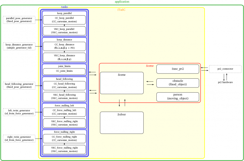 comanipulation layout An overview of all components involved can be found here
Execution
- Open two terminals
- go in both to itasc_comanipulation_demo_app:
roscd itasc_comanipulation_demo_app - (On a simulated PR2: open an extra terminal and start the PR2 in simulation
- run the PR2 low level controllers in the first (P controller with reduced gain):
./runControllers - run the application in the second terminal:
./run.sh - When your application has gone trough the configuration and starting phase, it will reach the running state: You should find a line on your screen saying "=>iTaSCFSM=>Running=>CompositeTaskFSM->Initialized State"
- To interact with the CompositeTaskFSM, you can send events to it: send events to interact (don't forget to go in and afterwards out!!!) eg.:
-
event_firer.itasc_common_events_in.write("e_parallelIn") -
event_firer.itasc_common_events_in.write("e_parallelOut") -
event_firer.itasc_common_events_in.write("e_obstacleForceParallelLimitsIn") -
event_firer.itasc_common_events_in.write("e_obstacleForceParallelLimitsOut") - more eventnames can be found in scripts/composite_task_fsm.lua => transitions
-
FAQ
Joint and segment mapping
A KDL::Tree has no order when asking it's segments (getSegments) which makes sense since there are branches on a tree. In practice, the getSegments returns the segments in alphabetical order, which is the default order you'll get the joint segments of the PR2 and the columns of the Jacobian matrices. The itasc_pr2 component maps the inputs and outputs from the robot side to this "general" order. For each chain between the base and the object frame you request from the component, the order is internally stored in the logical order from root to leave (a chain has an order of segments). Also in this case, the output towards the iTaSC side is mapped in the "general" order (the alphabetical order).Compilation problems
- Q: When I compile itasc_solvers, I get a linking error, he can't find choleski_semidfinite...
- A: You probably forgot to source the env.sh in the orocos_toolchain stack
| Attachment | Size |
|---|---|
| iTaSC_comanipulation_demo.pdf | 535.79 KB |
iTaSC FAQ
- Warnings at start-up: the following warnings can be ignored
- Lowering priority: if you're running on a non-real-time system, the priority will be reduced from RT to OTHER
- Conversion from float64[] to eigen_vector
- Port 'x' of 'y' and port 'z' of 'a' are already connected but (probably) not to each other: multiple ports connected to one port gives a warning, while this is common functionality
- 'addPort' Pose_ee_base: name already in use. Disconnecting and replacing previous port with new one: it won't ;)
- I get [EMERGENCY]
- This means that an error is caught by the state machine
- Have a look at the first [EMERGENCY] message and the line before that to figure out what went wrong
- Where do I define my Virtual Kinematic Chain?
- in your VKC_taskname component, eg. VKC_cartesian_motion (in the cartesian_motion/src package)
- Where do I put the feature coordinates in the code?
- They are implicit in your VKC definition, by defining feature coordinates and the degrees of freedom between them, you define the order in which the degrees of freedom are traversed, from one object frame to another. (cfr. going from one point to another, and you can only go in a direction once)
iTaSC videos
Videos of iTaSC examples and demonstrations. Click on the images below to see the video.
Human-robot co-manipulation with the PR2
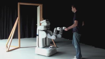 An example:: Human-Robot Comanipulation
